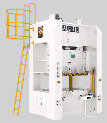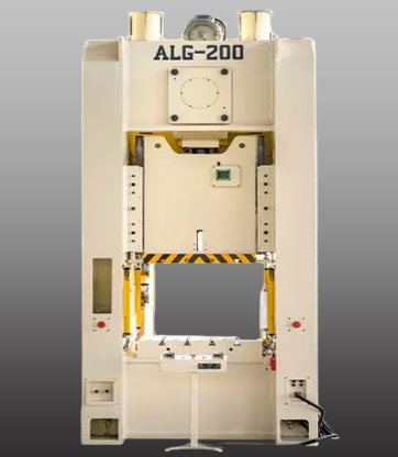


The ALG Single Crank H-Frame High Precision Power Press is engineered for exceptional accuracy, durability, and stability, making it ideal for demanding progressive stamping applications. Its robust four-column closed-frame structure ensures minimal deformation during high-load operations, maintaining superior precision over long production cycles. The press features extended six/eight-sided guide rails that deliver smooth slider movement and consistent accuracy. Equipped with an automatic grease lubrication system, it enhances operational efficiency while improving the working environment. Designed with advanced human–machine safety standards, the ALG Series ensures reliable, secure, and high-performance metal forming for modern manufacturing needs.
| Technical Parameter | ||||||||||||||||
| Item | ALG-160 | ALG-200 | ALG-250 | ALG-315 | ALG-400 | ALG-500 | ALG-630 | |||||||||
| Type | Ton | V | L | V | L | V | L | V | L | V | L | V | L | V | L | |
| Stroke | mm | 200 | 250 | 200 | 250 | 250 | 300 | 250 | 300 | 300 | 350 | 300 | 350 | 300 | 350 | |
| Stroke Per Minute | S.P.M | 20-50 | 20-40 | 20-50 | 20-40 | 20-40 | 20-35 | 20-40 | 20-35 | 20-30 | 15-25 | 20-30 | 15-25 | 20-30 | 15-25 | |
| Tonnage Rated Point | mm | 6 | 6 | 7 | 7 | 8 | 8 | 8 | ||||||||
| Max. Die Height | mm | 500 | 600 | 550 | 600 | 550 | 600 | 550 | 600 | 600 | 650 | 650 | 700 | 650 | 700 | |
| Slide Adjustment | mm | 100 | 120 | 120 | 120 | 150 | 150 | 150 | ||||||||
| Slide Area | mm | 700×650 | 900×800 | 900×800 | 1100×900 | 1100×900 | 1200×1000 | 1100×900 | 1300×1100 | 1100×1000 | 1400×1200 | 1200×1100 | 1400×1200 | 1400×1200 | 1500×1300 | |
| Bolster Area | mm | 900×800 | 1000×900 | 1000×900 | 1200×1000 | 1100×1000 | 1300×1200 | 1200×1000 | 1400×1200 | 1200×1100 | 1500×1300 | 1300×1200 | 1500×1300 | 1500×1300 | 1700×1500 | |
| Bolster Thickness | mm | 150 | 170 | 180 | 180 | 190 | 200 | 210 | ||||||||
| Side Opening Size | mm | 700×500 | 700×500 | 700×500 | 700×500 | 900×600 | 900×600 | 900×600 | 900×600 | 900×600 | 1000×600 | 1000×700 | 1000×700 | 1100×700 | 1100×700 | |
| Working Height | mm | 900 | 950 | 1000 | 1000 | 1100 | 1200 | 1250 | ||||||||
| Max. Upper Die Weight | kg | 800 | 1000 | 1500 | 1500 | 2000 | 2500 | 2500 | ||||||||
| Main Motor | KW×P | 15×4 | 18.5×4 | 22×4 | 30×4 | 37×4 | 45×4 | 55×4 | ||||||||
| Slide Adjust Structure | KW×P | 2.2 | 2.2 | 2.2 | 2.2 | 2.2 | 2.2 | 2.2 | ||||||||
| Rack Structure | One-piece | |||||||||||||||
| Required Air Pressure | kgf/cm² | 5~6 | ||||||||||||||
| Press Accuracy | CNS(JIS)1class | |||||||||||||||
| Press Dimensions (L×W×H) | mm | 2350×2450×4300 | 2500×2500×4650 | 2700×3000×5050 | 2700×3100×5100 | 3100×3300×5600 | 3650×3300×5800 | 3800×3600×6300 | ||||||||
| Die Cushion (Optional) | One Plate One Cylinder | |||||||||||||||
| Capacity | Ton | 10 | 14 | 14 | 20 | 20 | 20 | 25 | ||||||||
| Stroke Length | mm | 80 | 100 | 100 | 120 | 120 | 120 | 150 | ||||||||
| Cushion Area | mm | By Design | ||||||||||||||
| Accessories | Standard | Accessories | Optional |
| Hydraulic overload protection device | ● | Pneumatic Die Cushion Device | ○ |
| Inverter | ● | Quick Die Change Device (Die Lifter, Clamp And Die Arm) | ○ |
| Electric Slide Adjust Device | ● | Slide Knock-out Device | ○ |
| Electric Grease Lubrication System | ● | Anti-vibration pad | ○ |
| Electric Die Height Indicator | ● | Photoelectric Safety Device | ○ |
| Slide and Die Balancing Device | ● | Feeder | ○ |
| Rotary Cam Switch | ● | Uncoiler | ○ |
| Crank Angle Indicator | ● | Leveler | ○ |
| Air Source Connector | ● | Transfer Arm | ○ |
| Precut Counter | ● | ||
| Preset Counter | ● | ||
| Overrun Protection Device | ● | ||
| Tool Box | ● | ||
| Operation Manual | ● | ||
| Anti-vibration pad | ● | ||
| Misfeeding Detection Socket | ● | ||
| Die Room Light | ● |