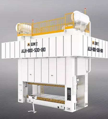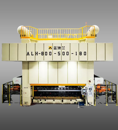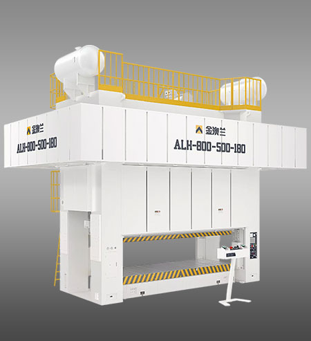


The ALH series press machine adopts a three-divided frame. The reinforcing rod is used to pre-tighten the top seat, the middle platform and the base into a whole, which has strong rigidity. The whole high speed stamping press adopts circulating thin oil lubrication and crankshaft transmission. the crankshaft driving device of the press machine comprises a motor, a crankshaft, and the flywheel fixedly connected to the clutch at one end.
The motor directly drives the flywheel to rotate through the V-belt, and the other end of the crankshaft is provided with a brake; the slider device is guided by the eight-sided guide rail, and two balance cylinders are arranged on both sides of the slider device. The cylinder of the balancer is fixed on the frame, and the piston is fixedly connected with the slider device; the upper beam is provided with a motor, a sprocket and a worm pair to adjust the die height.
| Technical Parameter | |||||||||||||||
| Item | ALH-250 | ALH-300 | ALH-400 | ALH-500 | ALH-630 | ALH-800 | ALH-1000 | ||||||||
| Capacity | Ton | 250 | 250 | 300 | 300 | 400 | 400 | 500 | 500 | 630 | 630 | 800 | 800 | 1000 | 1000 |
| Rated Tonnage Point | mm | 7 | 7 | 9 | 9 | 10 | 13 | 10 | 13 | 13 | |||||
| Stroke length | mm | 300 | 350 | 300 | 350 | 300 | 400 | 300 | 400 | 400 | 400 | 400 | |||
| Strokes Per Minute | s.p.m | 20-35 | 20-35 | 20-35 | 20-30 | 20-30 | 15-25 | 20-30 | 15-25 | 20-30 | 15-25 | 15-25 | |||
| Die Height | mm | 600 | 650 | 600 | 650 | 650 | 700 | 700 | 750 | 750 | 800 | 900 | 950 | 1000 | |
| Slide Adjustment | mm | 200 | 200 | 250 | 300 | 300 | 350 | 400 | |||||||
| Side Opening(F.B * H) | mm | 1100x850 | 1100x900 | 1250×1000 | 1300×1100 | 1500×1100 | 1500x1100 | 1600×1500 | |||||||
| Max. upper die height | kg | 1500 | 2000 | 1500 | 2000 | 3500 | 4000 | 4000 | 5000 | 6000 | 10000 | 10000 | 12000 | 10000 | 12000 |
| Main Motor | kw*4p | 30 | 37 | 45 | 55 | 75 | 90 | 132 | |||||||
| Working Area(L.R * F.B) | mm | 2500x1200 | 2500x1200 | 3000x1300 | 3000x1400 | 3200×1400 | 3800x1600 | 3800x1600 | |||||||
| 2600x1200 | 2600x1200 | 3200x1400 | 3200x1400 | 3800x1600 | 4000x1600 | 4000x1600 | |||||||||
| 2770x1250 | 2770x1300 | 3400x1400 | 3400x1500 | 4000x1600 | 4200x1600 | 4200x1600 | |||||||||
| 3000x1250 | 3000x1400 | 3500x1400 | 3500x1500 | 4500x1600 | 4500x1800 | 4500x1800 | |||||||||
| Frame Structure | --- |
Split |
|||||||||||||
| Accessories | Standard | Accessories | Optional |
| Hydraulic Over-load Protector | ● | Electrical Automatic Lubrication System | ○ |
| Inverter | ● | Pneumatic Die Cusion Device | ○ |
| Slide Adjust Device | ● | Foot Switch | ○ |
| Die Heigh Indicator | ● | Quick Die Change Device (Die Lifter,Clamp And Die Arm Shift Mode) | ○ |
| Balance Device | ● | ||
| Rotary Cam Switch | ● | Slide Knock-out Device | ○ |
| Crank Angle Indicator | ● | Misfeed Detection Consent | ○ |
| Power Supply | ● | Anti Vibration Press Mount | ○ |
| Electric Stroke Counter | ● | Photo-electronic Safety Device | ○ |
| Air source Recepatacle | ● | Feeder | ○ |
| Presrt Counter | ● | Uncoiler | ○ |
| Presrt Counter | ● | Leveler | ○ |
| Against Over-run Safety Device | ● | Machanism Hand | ○ |
| Maintenance Tool Box | ● | Die Room Light | ○ |
| Operation Manual | ● |