



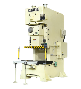
The ALP series of open-type fixed table presses are general-purpose presses for sheet metal stamping. They are suitable for various cold stamping processes such as shearing, punching, blanking, bending and shallow drawing. It is manufactured in strict accordance with Japanese JIS Class 1 accuracy standards and is superior to domestic standards.
The main components of our c frame punch press are all processed by imported CNC equipments. Japanese high-quality bearings and imported oil seal linings ensure the accuracy and longevity of the machine.
| ALP Series High Precision Compact Power Press Technical Parsmeter | |||||||||||||||||||||||
| Item | ALP-25 | ALP-35 | ALP-45 | ALP-60 | ALP-80 | ALP-110 | ALP-160 | ALP-200 | ALP-260 | ALP-260 | ALP-315 | ||||||||||||
| Model | V | H | V | H | V | H | V | H | V | H | V | H | V | H | V | H | V | H | V | H | V | H | |
| Capacity | Ton | 25 | 35 | 45 | 60 | 80 | 110 | 160 | 200 | 260 | 200 | 200 | |||||||||||
| Rated Tonnage Point | mm | 3.2 | 1.6 | 3.2 | 1.6 | 3.2 | 1.6 | 4 | 2 | 4 | 2 | 6 | 3 | 6 | 3 | 6 | 3 | 7 | 3.5 | 7 | 3.5 | 7 | 3.5 |
| Speed Changing | s.p.m | 60~140 | 130~200 | 40~120 | 110~180 | 40~100 | 100~150 | 35~90 | 80~120 | 35~80 | 80~120 | 30~60 | 60~90 | 20~50 | 40~70 | 20~50 | 50~70 | 20~40 | 40~50 | 20~40 | 40~50 | 20~40 | 40~50 |
| Stable Speed | s.p.m | 110 | 85 | 75 | 65 | 65 | 50 | 35 | 35 | 30 | 30 | 30 | |||||||||||
| Stroke | mm | 60 | 30 | 70 | 40 | 80 | 50 | 120 | 60 | 150 | 70 | 180 | 80 | 200 | 90 | 200 | 100 | 250 | 150 | 250 | 150 | 250 | 150 |
| Die Height | mm | 200 | 215 | 220 | 235 | 250 | 265 | 310 | 340 | 340 | 380 | 360 | 410 | 460 | 510 | 460 | 510 | 500 | 550 | 500 | 550 | 500 | 550 |
| Slide Adjustment | mm | 50 | 55 | 60 | 75 | 80 | 80 | 100 | 110 | 120 | 120 | 120 | |||||||||||
| Slide Area | mm | 300×220×50 | 360×250×50 | 400×300×60 | 500×360×70 | 560×420×70 | 650×470×80 | 700×550×90 | 850×630×90 | 950×700×100 | 950×700×100 | 1400×800×100 | |||||||||||
| Bolster Area | mm | 680×300×70 | 800×400×70 | 850×440×80 | 900×500×80 | 1000×550×90 | 1150×600×110 | 1250×800×140 | 1400×820×160 | 1500×840×180 | 1500×840×180 | 1800×950×180 | |||||||||||
| Shank Hole | mm | Φ38 | Φ38 | Φ38 | Φ50 | Φ50 | Φ50 | Φ65 | Φ65 | Φ65 | Φ65 | Φ65 | |||||||||||
| Main Motor | kw.p | 2.2×4 | 2.2×4 | 3.7×4 | 3.7×4 | 5.5×4 | 7.5×4 | 11×4 | 15×4 | 18.5×4 | 18.5×4 | 22×4 | |||||||||||
| Slide Adjust Device | Manual opearation | Electric driving | |||||||||||||||||||||
| Air Pressure | kg/cm² | 5~6 | 5~6 | 5~6 | 5~6 | 5~6 | 5~6 | 5~6 | 5~6 | 5~6 | 5~6 | 5~6 | |||||||||||
| Presses Precision | JIS GRADE 1 | JIS GRADE 1 | JIS GRADE 1 | JIS GRADE 1 | JIS GRADE 1 | JIS GRADE 1 | JIS GRADE 1 | JIS GRADE 1 | JIS GRADE 1 | JIS GRADE 1 | JIS GRADE 1 | ||||||||||||
| Presses Dimension | mm | 1390×920×2125 | 1450×990×2300 | 1650×1040×2390 | 1670×1090×2750 | 1820×1328×2980 | 1970×1458×3133 | 2390×1560×3610 | 2690×1790×4058 | 2865×1945×4433 | 2865×1945×4433 | 2900×1950×4600 | |||||||||||
| Die Cushion Capacity | Ton | — | 2.3 | 2.3 | 3.6 | 3.6 | 6.3 | 10 | 14 | 14 | 14 | 14 | |||||||||||
| Stroke | mm | — | 50 | 50 | 70 | 70 | 80 | 80 | 100 | 100 | 100 | 100 | |||||||||||
| Die Cushion effective area | mm² | — | 300×230 | 300×230 | 350×300 | 450×310 | 500×350 | 650×420 | 710×480 | 810×480 | 810×480 | 810×480 | |||||||||||
| Presses Weight | Ton | 2.1 | 3 | 3.8 | 5.6 | 6.5 | 9.6 | 16 | 23 | 32 | 23 |
23 |
|||||||||||
| Accessories | Standard | Accessories | Optional |
| Hydraulic Over-load Protector | ● | Pneumatic Die Cusion Device | ○ |
| Electrical Automatic Lubrication System | ● |
Quick Die Change Device (Die Lifter,Clamp And Die Arm shift mode) |
○ |
| Inverter | ● | Foot Switch | ○ |
| Slide Adjust Device | ● | Slide Knock-out Device | ○ |
| Preset Counter | ● | Anti Vibration Press Mount | ○ |
| Die Height Indicator (ALP below 60) | ● | Photo-electronic Safety Device | ○ |
| Rotary Cam Switch | ● | Feeder | ○ |
| Crank Angle Indicator | ● | Uncoiler | ○ |
| Electric Stroke Counter | ● | Leveler | ○ |
| Air source Recepatacle | ● | Machanism Hand | ○ |
| Against Over-run Safety Device | ● | ||
| Maintenance Tool Box | ● | ||
| Operation Manual | ● | ||
| Die Room Light | ● |
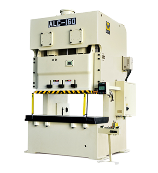
The ALC series of open type double crank c frame mechanical press is one of the best selling products of our company. The main drive gears, shafts, etc. are all enclosed at the top of the machine frame. After the body is welded with Q235-B, it will be tempered to eliminate the internal stress of the material. The main motor is mounted on the upper part of the frame, and the flywheel support, flywheel, clutch, etc. are installed on the rear side of the frame, and the flywheel is subjected to the assembly work after being tested for dynamic balance before assembly.
The gear part adopts a spur gear transmission mechanism, and the material is made of high-strength alloy steel, and the corresponding heat treatment is performed. Clutch is dry one-piece clutch brake. The clutch brake control system is controlled by a double valve. All bearing bushes are made of copper and wear resistant materials.
| Technical Parameter | |||||||||||
| Item | ALC-110 | ALC-160 | ALC-200 | ALC-250 | ALC-315 | ||||||
| Model | V | H | V | H | V | H | V | H | V | H | |
| Capacity | 110 | 160 | 200 | 250 | 315 | ||||||
| Rated Tonnage Point | mm | 5 | 3 | 6 | 3 | 6 | 3 | 7 | 3.5 | 7 | 3.5 |
| Stroke | mm | 180 | 110 | 200 | 130 | 250 | 150 | 280 | 170 | 280 | 170 |
| Stable speed | s.p.m | 35~65 | 50~100 | 30~55 | 40~85 | 25~45 | 35~70 | 20~35 | 30~60 | 20~35 | 30~50 |
| Die Height | mm | 400 | 435 | 450 | 485 | 500 | 550 | 550 | 605 | 550 | 605 |
| Slide Adjustment | mm | 100 | 100 | 120 | 120 | 120 | |||||
| Slide Area | mm | 1400×500×70 | 1600×550×70 | 1850×650×95 | 2100×700×95 | 2100×700×95 | |||||
| Bolster Area | mm | 1800×650×130 | 2000×760×150 | 2400×840×170 | 2700×900×170 | 2800×950×170 | |||||
| Main Motor | kw.p | 7.5×4 | 11×4 | 15×4 | 18.5×4 | 22×4 | |||||
| Air Pressure | kg/cm² | 5~6 | 5~6 | 5~6 | 5~6 | 5~6 | |||||
| Presses Precision | Ton | JAPAN JIS CLASS 1 | |||||||||
| Die Cushion | Two plate & two cylinders | ||||||||||
| Capacity | Ton | 3.6×2 | 6.3×2 | 10×2 | 14×2 | 14×2 | |||||
| Stroke | mm | 70 | 70 | 80 | 100 | 120 | |||||
| Die Cushion work part dimension | mm | 350×235×2 | 410×260×2 | 540×350×2 | 640×470×2 | 640×470×2 | |||||
| Accessories | Standard | Accessories | Optional |
| Hydraulic Over-load Protector | ● | Electrical Automatic Lubrication System | ○ |
| Manual drive Lubrication System | ● | Pneumatic Die Cusion Device | ○ |
| Inverter | ● | Presrt Counter | ○ |
| Slide Adjust Device | ● | Presrt Counter | ○ |
| Die HEIGH Indicator | ● | Foot Switch | ○ |
| Balance Device | ● | Quick Die Change Device (Die Lifter,Clamp And Die Arm shift mode) | ○ |
| Rotary Cam Switch | ● | Slide Knock-out Device | ○ |
| Crank Angle Indicator | ● | Misfeed Detection Consent | ○ |
| Electric Stroke Counter | ● | Power Supply | ○ |
| Air source Recepatacle | ● | Anti Vibration Press Mount | ○ |
| Against Over-run Safety Device | ● | Photo-electronic Safety Device | ○ |
| Maintenance Tool Box | ● | Feeder | ○ |
| Operation Manual | ● | Uncoiler | ○ |
| Leveler | ○ | ||
| Machanism Hand | ○ | ||
| Die Room Light | ○ |